Ref: AFV Club #35293 Israel Defense Forces M109A2 Doher self-propelled 155 mm howitzer
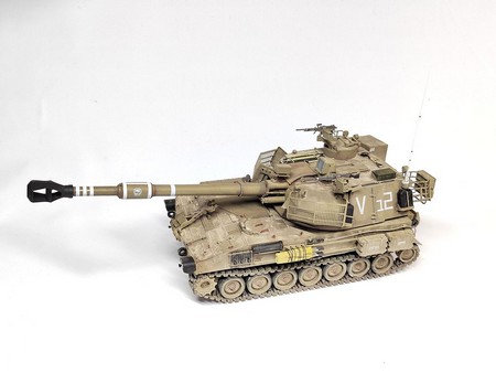
The M109A2 Doher is an evolution of the M109A1/A2 in IDF service. Entered in service in 1993, it was developed after IDF cancelled their participation in the US HIP program which eventually led to the M109A6 Paladin. The aim of the modernization was to reach the same level of performances as those of the Paladin in terms of range and accuracy.
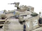
The Doher features improvements such as a new electric system, a new fire control system, an electrically operated travel lock, a raised vehicle commander cupola, a diesel generator at the rear right corner of the turret in place of a stowage basket, the addition of a basket on the rear right side of the turret and an additional MG for the loader. According to the original version, M109A1 or A2, the Doher is equipped with the pop-up sight or the panoramic sight in an armored cover.
The Doher is armed with a 155 mm 39 calibers gun. It can fire up to 30 kilometers and carries 39 rounds. The secondary armament is made of 2x 7.62 mm MAG58 mounted on the commander cupola and a swing mount to the left of the loader station.
The crew of the Doher is 7: 1 driver and 6 gunners.
The Doher has been used in each and every conflict conducted by Israel since its entry into service.
The kit
Released by AFV Club in 2016, it re-uses many sprues of previous references. It includes 22 green plastic sprues, 1 clear sprue, 1 vinyl sprue, 2 vinyl tracks, 1 aluminum gun barrel, 1 photoetched parts plate, 1 length of thread for the cable, 1 sprue of polycaps, 3 sheets of decals, 1 instructions booklet and 1 poster with the boxart.
The cast is good with thin mold lines. Unfortunately there are many ejection pin marks which are very often ill-placed. The level of detail is good with many very thin parts. The fit is quite good however some large parts require some work to fit.
The instructions are divided into 47 steps and feature some mistakes. An historical background is included on the front page and a diagram with the evolution of the M109 versions is provided at page 3. AFV Club give color indications to paint many details in the assembly steps.
The PE parts are thin and fit well to the plastic parts. However some assemblies are tricky because there is no marks to glue the parts together.
Three decoration options are proposed with units identification. The color references are provided in 6 different ranges.
The build
It begins with the assembly of the lower hull at steps 1 to 4. At step 1, you need to be careful not to cut the positioning rods of parts B24. At steps 2 and 3, you have to drill the sides of the hull from inside. Unfortunately AFV Club omitted to mold the drill marks. The best is not to drill and glue the parts later after having estimated their right locations on the instructions drawings or reference pictures.
At step 5 the suspension assembly is not an issue. The choice by AFV Club of functional torsion bars is not useful.
At stpe 6 you have to get rid of ejection pin marks on the inner faces of the roadwheels and idlers.
At step 7 you assemble the roadwheels and sprockets. I prefer doing it later when those are parts are painted.
Steps 8 to 12 deal with the installation of the hull roof and the various details on it. At step 8 you need to drill out not only 1 but 2 holes in part B32 to glue the cap B11. A thorough study of the drawing at step 9 is necessary because it is a bit confusing. Step 10 is not an issue. However to facilitate the coming painting I didn't glue the headlights glasses. At step 11 the extinguisher handle C10 is also numbered C45. Part B21 is already molded on the hull roof and so it is useless. At step 12 you have to guess the locations of nearly all the parts. For the foot-steps C6 the drawing shows positioning marks which are not molded on the hull front. Concerning the PE parts G2 and G3 you have to look at the drawing to place them. Then part B2 can be glued between the both plates.
At step 13 you have to assemble the travel lock. Despite the numerous parts, it is not complicated. You need to thoroughly clean the parts and the ejection pin marks. The handle on the main part E29 is very fragile. Theoretically the travel lock should be mobile. I preferred glue it in the firing mode.
Steps 14 et 15 do not need any comments.
Steps 17 and 18 deal with the rear spades. You must use the glue sparingly so they remain mobile. The hooks B30 must not be glued yet because they definitely lock the spades. It is better to wait until the painting stage.
Step 19 to 22 deal with the detailing of
the hull sides. Because of the lack of positioning holes for the rails and the
other accessories, all the positioning rods are removed. On the right side, the
brackets for the aim stakes are positioned with reference pictures. The gap
between them is checked with a stake. The upper rail is glued 5 mm under the
upper hull edge. The lower rail is glued using part G18 to check the gap with
the upper rail. The wooden crates are assembled after sanding of the sides
edges.
On the left side the cable brackets according reference pictures. The cable is
made of naval thread since the bit of thread issued by AFV Club is too short by
5 cm. The cleaning rod E44 is not installed yet. You need to sand its
circumference so it can be inserted in the shell casing D8. However if you
install the cleaning rod sections of the turret roof, you must use part E44.
Even though AFV Club do not mention it, it is possible to use at least one
stretcher provided in the box.
Step 23 deals with the tracks assembly and the last details at the rear of the hull. The tracks are too long by 2 links. Once the links are removed, the ends are glued back and the junction is strengthened with a brass axis. To get the tracks sag you need to glue them on top of the roadwheels. At the rear you have to thin the hinges of the mudguards C60 and C61.
Steps 24 to 28 deal with the gun assembly.
The muzzle brake assembly is a bit tricky to have a perfect alignment of part
D27 with the sides. At step 26 you assemble the breech. The instructions call
for 2 parts B27 where you need 4. At the front of part D20 a long rod must be
cut. The breech can be represented closed or open. However this is not really
interesting as there is no interior.
At step 27 the muzzle velocity radar is made of parts E12 and E14. AFV Club show
the vertical support but forget to mention this is a third part B3.
Step 29 concerns the turret assembly. Beforehand you have to fill some holes and delete some molded details. The turret hull is slightly warped and the bottom of the gun aperture is larger than the top. Consequently the fit to the base Q2 is not good. It is advised to start gluing by one side and then to turn around till the other side. The rear panel B31 is then glued and because the fit is not perfect there is a small gap to fill.
At step 30 the hardest is to glue the bolted frame around the gun.
At step 31 AFV Club give the possibility to build the panoramic sight or blank off the hole.
At steps 32 and 33 most of the details must be positioned without any marks. AFV Club provide a drawing with the parts in place to avoid mistakes.
At step 34 and 35 hooks B9 and B1 are inverted. Those parts are very fragile. The rear left basket is made of 8 different parts.
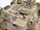
At steps 36 and 37you have to assemble the generator support and the generator itself. Part E20 (control panel) must be thinned so it can be inserted in its location. The generator is not glued yet to facilitate the painting of the control panel.
At step 38 the tools are not glued yet. They will be after the painting. The shovel Q30 does not have the rod to insert into the turret roof. AFV Club do not mention part Q27 whereas it is present on the painting instructions and the boxart.
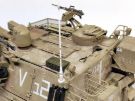
At step 39 you assemble the right turret side basket and glue to it an antenna base. For the latter there is a plastic plate with grooves in it which must be well oriented for the antenna to be vertical. AFV Club omitted to mention it. For a better realisme I drilled out the pickaxes heads.
At step 40 the installation of the dust cover is difficult. Even if it is a vinyl part it is stiff and does not allow the gun elevation without having a weird look.
At step 41 you must removed the ejection pin marks on the MG mount C5.
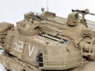
At step 42 and 43 you assemble the front turret baskets. The tubular structures build quite easily. Unfortunately on my sample some tubes were warped. To glue the PE grilles it is better to start from the top.
Steps 44 and 45 are dedicated to the MGs assembly. On the cradles U52 you need to remove the spotlights brackets. The reference pictures never show them. To install the loader MG you have to slightly raise the base at the front of support E13.
Step 46 is the final assembly step. Nonetheless there is a step 47 concerning the painting of the individual arms (Tavor and M4) as well as the assembly and painting of the propellant containers for which AFV Club provide decals.
The decoration
AFV Club propose 3 options without unit
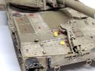
information. The base color is AK Sinai grey 1982. A preshading is done with
XF-10 Flat brown. Then after a new coat of Sinai grey highlights are done with
the base color enlightened with some XF-57 Buff. Some details are even more
enlightened with a brush. Then colored details (black, yellow and red) are
painted according to the instructions. Several wooden shades are applied to the
tools.
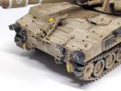
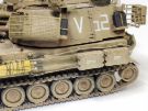
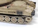
The tracks are painted with various shades of earth and sand. The rubber pads
are painted XF-63 German grey to give them a worn and dirty look. The guide
teeth as well as the contact surface with the roadwheels are rubbed with XF-56
Metallic grey.
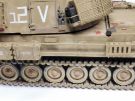
For the decals application it is advised to trim the decals to avoid the silvering.
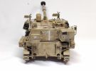
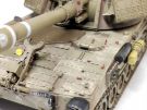
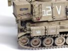
For the weathering I applied a dark brown wash to enhance the details. Then the dusty effect has been done by using Ammo Syrian ground and North Africa dust pigments.
Conclusion
This model is rather disappointing because of the numerous approximations to place the Doher specific parts and the too high amount of ill placed ejection pin marks. The most detrimental problem is the lack of holes to position the rails and the other accessories on the hull sides. The cable too short is not acceptable for a model released in 2016. The tracks are too long and even if with a small amount of work you can shorten them, AFV Club should have avoided the use of vinyl on this type of running gear characterized by a heavy sag.
Reference : Rochev and Doher, M109A1/A2 Rochev and Doher in IDF service, Michael Mass and Adam O'Brien, Desert Eagle Publishing ISBN 978-965-91635-6-4
Click on a thumbnail to see the full sized picture
|
|
|
|
|

|
|
|
|
|
|
|
|
|
|
|
|
|
|
|